This is to verify the pin numbering and its matching the simplified police circuit diagram. For the sake of this post we will adopt the same configuration as posted on Brock's simplified wiring diagram. The plug is setup with the locking latch at the top and the pins numbered from Top Left to Bottom Right
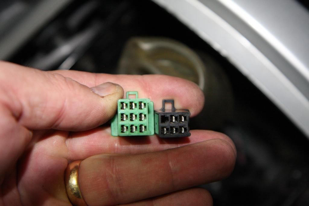
The details for the 6 pin plug (5 used) is 100% correct. So now only focusing on the 9 pin connector above. Top left is pin 1 and bottom right is pin 9 of the green connector.
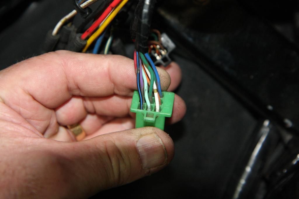
We can see the colours.
Pin 1 is Black/Blue Trace
Pin 2 is Light Green
Pin 3 is White/Brown or Gold band
Pin 4 is Purple
Pin 5 is Green (Chassis Ground)
Pin 6 is Orange/Green band. Hard to see but this next photo confirms as I rotate the connector to the left.
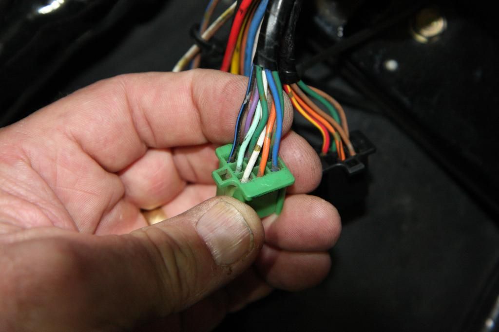
What about the pins 7,8 & 9?
This next photo continues to rotate the connector this time through a further 180. This is harder to orientate initially but follow it round.
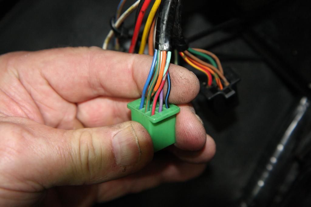
Pin 7 is Red
Pin 8 is Green/Orange stripe
Pin 9 is Blue.
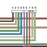
It is my belief that the above should be numbered as follows.
1 6 8 9 4 5 7 3 2
I think I have it right now. If the above numbers were used the drawing would be spot on I believe.