Thought I'd post my latest project for two reasons... Feedback to see what the community could add/change to improve my initial attempt, and to share one method to wire up a trailer outlet with little cost (under $50) for anyone considering it.
Got a 2002 ST1300 from one of the local dealers earlier this year which came with a towbar, but they had disconnected it and in the process sliced the trailer wiring to get it off. Probably a good thing in hindsight, because the wiring was just piggybacked to the tail lights which I'm led to believe is not the ideal way for the electrical system to cope.
Having read around, I've made my own relay, but I've got to warn you that some may find the following pictures disturbing. It's very messy. Spaghetti messy.
I found
this thread on ST-Owners.com and figured the logic and method of making your own relay could possibly be done by a novice like me. BTW - I've uploaded the images from that thread to an image hosting service rather than leech off the ST Owners server. If that's not the preferred way, let me know and I'll post the links to the original images.
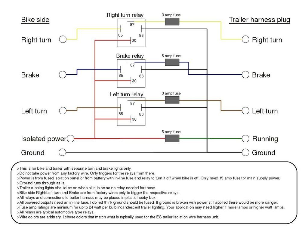
The two images in that thread I've used for my wiring are...
The relay wiring:
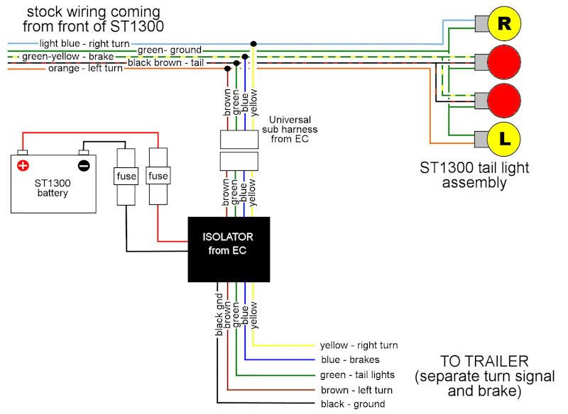
And the connections to the ST1300 wiring:
I've decided not to fuse earth as shown in the second image because I've never seen it on any car radio I've wired before. If anyone thinks this should be fused, let me know.
So... I've headed out to Jaycar with a basic shopping list and come back with
* 7-core trailer wire
*
3 fused relays* 12v red and black wire
*
project box*
12 pin auto socket* various female spade connectors
* a mini-fuse piggyback
* some plastic wiring splices
In hindsight, the 12v red and black wiring was a way heavier gauge than I needed, and created some problems when trying to connect everything together.
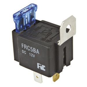
The fused relays (SPST) got my attention by having the fuse I required already built in...
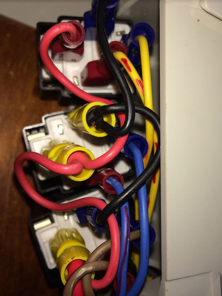
Ok, so this is where the spaghetti "mess"-tern begins. I've decided red wire for power, black for earth (naturally) and following the diagrams - yellow/right, brown/left, blue/brakes, green/tail. As per the diagram, left, right and brake will have a relay while the tail light will be powered directly to the 12v supply. By following the wiring in the first image, it's possible to solder and/or crimp the left/right/brake relays together with the power (pin 30) and earth (pin 86) wired in series. I then connected pins 85 with a single wire to go to the 12 pin connector and used a red permanent marker to distinguish them from the wires to pin 87.
Brace yourself... heres what it looks like in the project box.
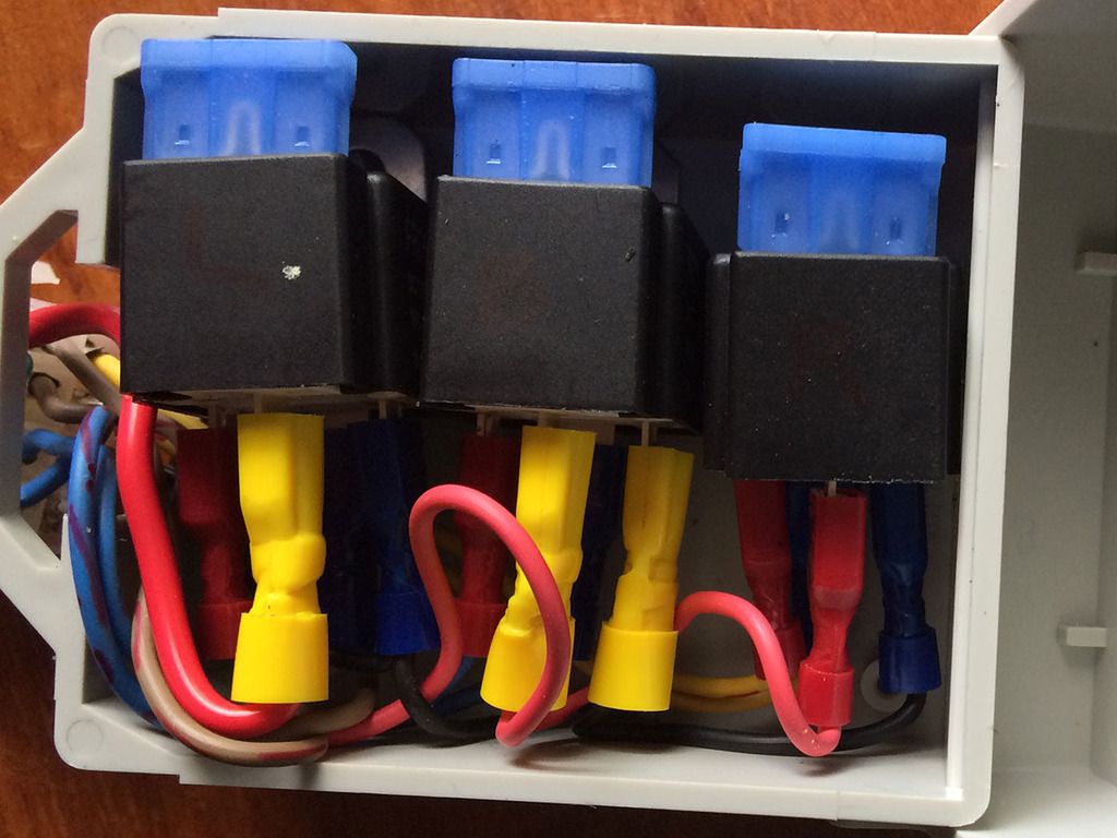
And here's the wiring from the base of the relays:
Ok, now it can be hooked up to the 12 pin connector:
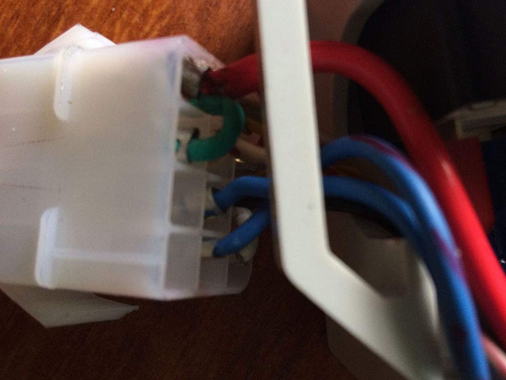
You can see in the photo that I've bridged the incoming 12v out across 2 pins to supply the relays and to power the tail light directly (earth similarly bridged across 2 pins). If anyone's interested in how I wired each side of the 12-way connector, l can post it.
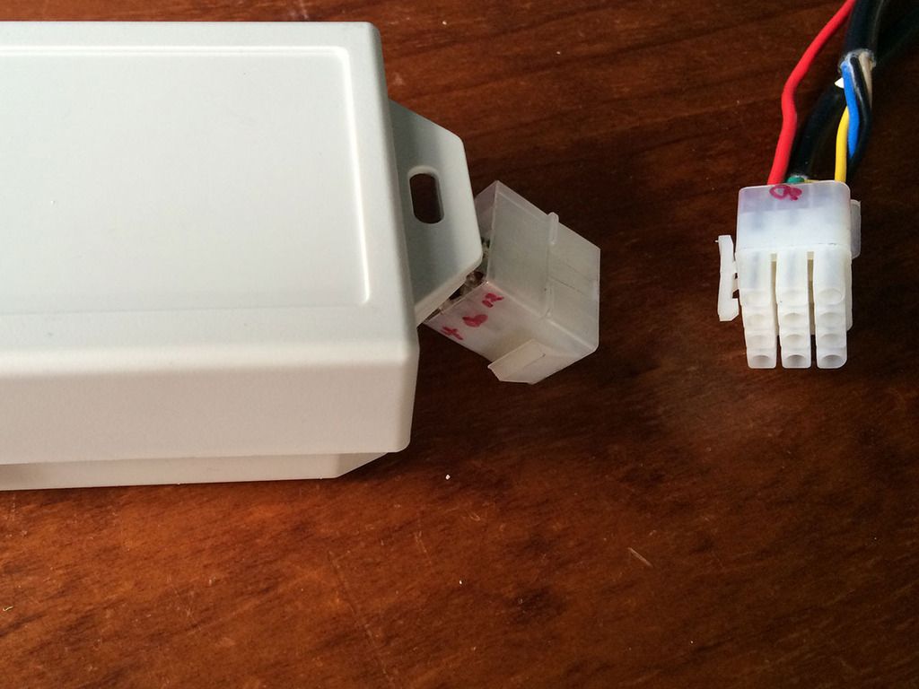
Now that's complete we can hide the mess by closing the lid - once you've written the pin connections inside the box for future reference/troubleshooting, of course!
So, we can now hook up the box to the bike. The second image in this post has the wiring colour codes in the tail for sending the "signals" to the relays.
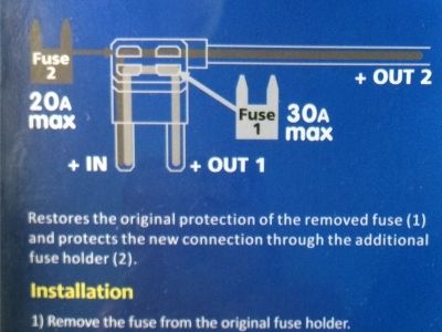
For power, I've tried a piggyback fuse connector. This one keeps the "donor" fuse doing it's original job...
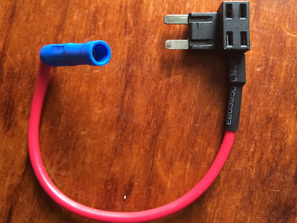
Wiring in the fuse is as follows:
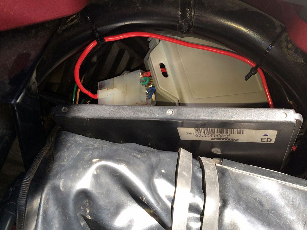
So now the box fits neatly in the tail, easily accessed if there's a blown fuse:
Some questions for those with more knowledge than me:
Should I replace the 15amp fuses in the relays with smaller fuses? As described above, is a fuse on the ground wire recommended or to be avoided?
Feedback/praise/ridicule/questions/OH&S advice all welcomed!


